Categories
Blog

The Importance of Clean Oil in a Vacuum Pump

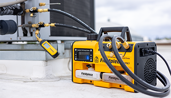
A vacuum pump is a powerhouse machine that removes air, gases, moisture, and contaminants from a system to create a clean environment for refrigerant. These efficient and powerful machines need clean oil to perform at their peak. When oil becomes cloudy or saturated, the pump won’t work as well, and pulling a deep vacuum takes longer.

Double-duty Oil

The oil in the vacuum pump acts as both a lubricant and as a sealant. It keeps the pump vanes (rotor blades) lubricated and helps keep a proper seal for an optimal vacuum. The deep vacuum that the pump creates helps push moisture and non-condensables from the system to the pump, ensuring the system is ready for refrigerant. This process contaminates the oil in your vacuum pump, which negatively impacts the pump’s performance and efficiency by compromising its internal seal. Pumps with contaminated oil will struggle to create a strong pressure differential, leading to increased evacuation time and eventual damage to the pump.

When to Change the Oil

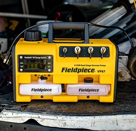
The need to change your oil will depend on several factors. The most effective way to maximize performance and efficiency of your vacuum pump is to change the oil after each evacuation. In humid environments systems are more likely to contain moisture. Systems with more moisture and non-condensable contaminants present will contaminate your oil faster, requiring more frequent changes to maintain performance. Moisture contamination is easy to spot because the oil looks milky or cloudy. Other contaminants can sink to the bottom of your oil reservoir, so vacuum pumps with better reservoir visibility, such as the large window on the Fieldpiece vacuum pumps, allow for more accurate monitoring.

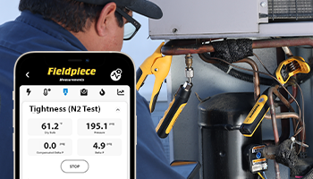
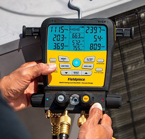
Another key indicator that it’s time for an oil change is pump efficiency. When pulling a vacuum, if the rate at which your microns are decreasing starts to level out, this could signal the need to change oil. When pump efficiency starts to wane, pulling a deep vacuum becomes more time-consuming. Note that the time to pull a vacuum will vary depending on the size of the system, atmospheric conditions such as humidity, and the efficiency of your evacuation setup.

Oil Changes on the Fly

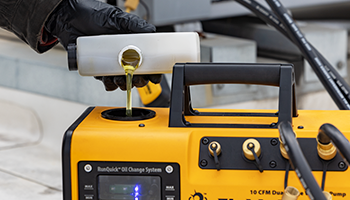
Some pumps on the market allow the oil in the pump to be changed while it’s pulling a vacuum, like the RunQuick® oil change system on Fieldpiece vacuum pumps. Towards the end of the evacuation is when you need fresh oil the most, so oil changes on the fly are key to working faster and smarter.

Get a Vacuum Pump that Works for You

Since clean, dry oil is crucial for faster evacuations, consider vacuum pumps that make oil changes quick and hassle-free. Fieldpiece vacuum pumps are powerful, portable and offer oil changes on the fly, saving you time on every evacuation. See the entire line of pumps, oil and other HVAC tools built and designed for techs.

Categories
Blog

Three Tips for Your Next System Evacuation 

For refrigerant heating and cooling systems to work correctly and optimally, the refrigerant must be free of air, nitrogen, moisture, and contaminants. Therefore, before charging a system, it’s critical to evacuate the system with a vacuum pump to create a clean and sealed environment. Here are a few tips and best practices to make your next evacuation faster and more effective. 


Tip 1: Purge with Nitrogen 

Moisture in a system can drastically increase the time it takes to pull a vacuum and removing that moisture and other contaminants is a crucial step to saving time. To ensure that the system is free of excess oxygen, refrigerant, moisture, and other contaminants, purge it with nitrogen. This is different than flowing nitrogen or conducting a nitrogen pressure test. To purge, connect a nitrogen tank and flow nitrogen through the system at around 100 PSI. This allows nitrogen to flow into one side and then out the other. The movement displaces excess oxygen and air. It also removes any dangerous gases and ensures the system is dry. While performing this purge, be sure to keep the area well-ventilated. Nitrogen can displace oxygen and create a dangerous environment for techs or other occupants, so always keep this in mind. 


Tip 2: Triple Evacuate 

When working in humid environments or on systems with significantly more moisture, a triple evacuation is a great way to remove the moisture entirely. This is an industry requirement for some OEMs, and one of the most effective techniques for systems with high moisture content. Start by sealing the system off and pulling the system down to a vacuum of between 1000 and 2000 microns. Then, break the vacuum by introducing nitrogen for 5 minutes at 5 PSIG. Perform another evacuation to 500 microns, and then break it again with nitrogen for five minutes. Perform a third evacuation and pull the system down to between 200 and 300 microns. Let the system sit for 10 minutes, or longer for larger systems. Performing the triple evacuation purges with nitrogen helps the excess moisture and other contaminants vent out of the system. Not to mention, systems with less moisture allow for pulling a vacuum faster, saving you time on the job. 


Tip 3: Change Your Oil 

Within a system is not the only place where moisture can impede evacuation efficiency. High moisture content in your vacuum pump oil considerably reduces your pump’s ability to pull a deep vacuum quickly. Cloudy oil is a sign of moisture buildup, a natural occurrence in used oil. Vacuum pumps with clean, dry oil can maintain a higher pressure differential, speeding up the vacuum process and allowing for a deeper vacuum. This means more frequent oil changes directly improve your ability to evacuate systems quickly, once again saving you time on the job. With Fieldpiece vacuum pumps featuring the RunQuick® oil change system, you can change oil in seconds without losing vacuum.  

Effective tools are only part of an effective service. Staying informed and up to date on best practice is just as important, so we hope these tips help make your system evacuations easier, faster, and better! 


Categories
Blog

Know You’ve Got It with New Valve Core Removal Tools

During peak cooling season, removing a valve core on the job is as common and necessary as finding shade. Removing the core opens the valve completely, eliminating flow restrictions for faster recovery, evacuation, and charging. To simplify your job, Fieldpiece has introduced a new lineup of three valve core removal tools (VCRTs) that eliminates the trial-and-error process (and frustration) often faced with other tools.

Locked In
With a press-fit gasket design, the tip of the capture rod locks in the valve core the first time, every time. No adjustments necessary. With the valve core reliably secured, it won’t fall off within the tool or get lost once it’s removed. All models of Fieldpiece VCRTs have a magnetic cap on the capture rod to safely store the locked-in core on the system housing, keeping it clean and handy. PRO TIP: best practice is to always replace the removed valve core with a new one.

Seeing is Believing
Almost every technician has played the “Did I Get It?” game when removing the valve core. With no way to confirm that the core has been successfully captured before removal, you are left to remove the rod and check, releasing some refrigerant with each attempt. Also, if the core has fallen off within the tool, a quick (and dangerous) opening of the valve on a charged system can eject the core at high speed. Did we mention the frustration that sets in after multiple failed attempts to remove the core? To eliminate this annoyance, the Fieldpiece VCG1 and VCG2 feature an integrated sight glass. You can clearly see the end of the rod through the sight glass and confirm the valve core is attached before extracting it – sanity intact. The sight glass can also be used to verify that refrigerant is flowing.

Two’s Company
The VCG2 model also includes a second ball valve on the side port. This convenient addition allows you to easily isolate and protect a connected vacuum gauge from refrigerant contamination. Since the second ball valve is integrated into the VCRT, you no longer need to add a fitting to gain an isolation valve, which increases bulk and introduces a new potential leak point.

Made to Fit your System
All three of the new Fieldpiece VCRTs come standard with a 1/4” service port fitting that may be swapped with an optional 5/16” fitting on the jobsite. You no longer need to purchase and haul additional VCRTs to accommodate different system ports, simply keep the swappable fitting in your toolkit. Fieldpiece VCRTs are the right tool, every time.

Thumbs up!
Inserting a core when a system is pressurized can be awkward, except when you have a comfort spinner! The VC1G and VC2G tools feature a rubber-coated, free-spinning cap that lets you use your thumb to hold the capture rod in place, against pressure and easily thread the core with your other hand. Another tech-friendly feature from Fieldpiece.

It’s a Fieldpiece
The VCRT lineup is another addition to our arsenal of rugged tools designed to make life easier for technicians everywhere. We stay committed to innovating in the HVACR industry and providing tools and instruments that survive the test of time while making jobs easier, faster and better. Learn more about the new VCRT and more at fieldpiece.com.

Categories
Blog

Before the Charge: A Guide to Nitrogen Leak Testing

Fieldpiece is always looking for innovative ways to make tech’s job easier, faster and better, and the combination of Job Link Probes and the Job Link System App do just that. Did you know that you can now use these tools to conduct a temperature compensated, nitrogen pressure leak test? Let’s walk through when to run a pressure test and some of the key steps in the process.

If you’re conducting a service call and have made repairs on a system, it’s important to make sure that it’s a clean, dry, and tight system – especially if you brazed new copper, added flared connections, or repaired other mechanical connections. A nitrogen pressure leak test is an excellent way to ensure that the system doesn’t have any leaks before charging it.

It’s recommended to run a pressure test, also called a tightness test, after a leak has been detected and repaired, or on new installs before charging with refrigerant. The test fills the system with nitrogen under pressure to determine whether it can hold that pressure over time, verifying there are no leaks. Nitrogen is an inert gas and is much safer and cheaper to use than refrigerant.

Before adding nitrogen and conducting a pressure test, record the initial pipe temperature and determine the length and volume of the tubing that is being filled to calculate the amount of nitrogen you will need. Then, make sure there aren’t leaks at the Schrader cores. You should also test your hoses and anything else connected to the system during the test.

Start by purging the system with nitrogen. This is different than flowing nitrogen – that’s at a much lower pressure. Purging allows nitrogen to flow into one side of the system and then out the other. This displaces all excess oxygen and air in the piping. Since you’re working with gas under pressure, be sure to work safely. Any gas under high pressure should be handled carefully and transported per the Department of Transportation guidelines.

After purging, replace the valve cores if you removed them, and attach a pressure regulator to the nitrogen tank and a charging hose to the service port. Be sure to use a regulator that is made for nitrogen and properly sized for the target pressure. Attaching a Job Link® System JL3PR Pressure Probe to the system can offer additional accuracy compared to the standard regulator dial. To monitor temperature, connect a Fieldpiece JL3PC Job Link® System Pipe Clamp to the system. Note that you can also use your Fieldpiece SMAN® digital manifold to run a nitrogen pressure test.

Once the system is prepared, start to slowly pressurize the system. Start with 100 psi and let the system sit for a minute. Then add another 100 psi and let it sit again. Typically, the recommended test pressure range falls within 200-600 psi, but check the system manufacturer’s specifications. If you’re pressurizing the low side of the system, use the manufacturer’s rated test pressure. Note that a stepped process that gradually increases pressure is not only safer, but it can also prevent wasting time and nitrogen.

Once the system is under pressure, isolate it by removing the charging hose and capping the Schrader port. If you’re working on a residential system, let it sit for 30 to 60 minutes. Some larger, commercial systems require a nitrogen pressure test to sit for 24 to 48 hours. Check with the manufacturer’s recommendations for the exact time needed.

If the system needs to sit for an extended period, temperature fluctuations in the environment will affect the pressure of the nitrogen in the system. Make sure to compensate for these changes in pressure before concluding that a system is leaking. Note that the new pressure test feature in the Job Link System App compensates for temperature fluctuations, as does the Fieldpiece SMAN digital manifold.

If you see a drop in the temperature compensated pressure over time, it means there is a leak. Bubble test every fitting and connection to find the source of the leak. This includes every field-fabricated joint in the system. Any of these could be a potential leak point.

When performed correctly, a nitrogen pressure test is an easy and safe way to determine if a system can be charged with refrigerant. Download the latest Fieldpiece Job Link ® System updates from the app store to include the nitrogen pressure test features. Learn more at www.Fieldpiece.com.

Categories
Blog

A Quick Primer on Furnace Pressure Switches

Now that we’re in the middle of heating season, we bet you’re making more and more service calls for malfunctioning or under-performing furnaces. During these calls, it’s important to make sure that the furnace pressure switch is functioning as intended.

The furnace pressure switch opens and closes to prevent harmful combustion gases from entering the living space and to prevent furnace fires and potential explosions. An elastomeric diaphragm within the switch remains open when the furnace is off. When the furnace is turned on and functioning correctly, the diaphragm operates under the correct pressure created by the draft inducer motor. This completes an electrical circuit that allows the furnace to ignite for the heating cycle. If the pressure conditions are outside of manufacturer specifications the switch will open to initiate a shut-down to prevent the creation of an unsafe environment for residents and technicians.

When examining a pressure switch, start by using a CO detector to check for harmful gases to ensure you can work safely. Then, run the furnace through its cycle. If you notice erratic ignition cycling when there is a call for heat from the thermostat, that may indicate that the diaphragm or the pressure switch is old and could need replacing. Also, check to make sure that the furnace is properly vented.

If the furnace tries to cycle but stops during start-up and then shuts down, it may be because of a faulty pressure switch. In this case, check for a clogged hose port, a blockage in the flue, corrosion or debris blocking the switch. A bad spring could also be the culprit. All of these should be examined.

To test a pressure switch, an ideal tool is the Fieldpiece SDMN6 Manometer Dual Port w/ Pressure Switch Tester. This versatile manometer allows a tech to use the ports to quickly connect to the switch while it’s still in place, confirm that it’s operating correctly and even verify it is performing within manufacturer specifications.

When a pressure switch is faulty and requires replacement, a good piece of advice is to keep a supply of universal pressure switches in the truck. This quickly helps get a furnace back to operating properly. When replacing a faulty switch with a universal switch, it’s best practice to notify the property owner. Given the importance of the proper fit and setting of a pressure switch, some owners may be willing to wait for the procurement of an OEM part for additional piece of mind, or even request a future update from a universal switch to the OEM. This will allow for their system to be operable until a follow-up call can be made with the requested pressure switch.

The pressure switch is an important piece of every heating system and knowing how to examine, test, calibrate and replace them is a critical job for techs and the Fieldpiece SDMN6 is the best tool for the job. Learn more about the SDMN6 at Fieldpiece.com.


Categories
Blog

Measuring HVAC Total External Static Pressure with a Digital Manometer

Measuring a system’s static pressure is a bellwether to HVAC system performance, similar to measuring your blood pressure to determine overall health. Static pressure is the resistance against airflow in an HVAC system that must be overcome to deliver warm or cool air to a conditioned space. Manufacturers of air handlers and furnaces design their systems for optimal performance at or below a specified Total External Static Pressure (TESP). And measuring TESP with a digital manometer is just one way to help techs diagnose and troubleshoot HVAC systems. 


How to Measure TESP

TESP is measured using a dual port manometer with probes inserted at the return side, typically after the filter, and the supply side of the furnace or air handling unit. Test ports will likely need to be created, so it’s important to be cautious and drill outside of the manufactured box in order to not puncture the coil, blower or heat exchanger. While the optimal TESP will vary based on the equipment, a typical system will run most efficiently at or below 0.5” water column (w.c.). What that means is that you don’t want to see a static pressure buildup in the return and supply that is higher than the specified TESP because it’s harder for the blower to work as designed and effectively move air. 


Zero and Align Probes

Before inserting the hoses or probes into the test ports, hit the “zero” button on the manometer to make both port 1 and port 2 equal relative to each other and to the atmosphere. Insert the manometer hoses or probes so that the openings are perpendicular to the direction of airflow. More repeatable and accurate results can be achieved with static pressure probes instead of hoses. The probes with a magnetic base and arrow marking that aligns the probe tip into the airflow provide the highest guarantee of successful placement. 


Taking Measurements

Once the probes are inserted and the system is operating at the highest airflow speed, wait approximately three minutes for the system to stabilize before taking measurements. Note that after a few minutes field manometers will drift, so it’s also important to reset with the “zero” button before each use. 

Add the absolute value of the port 1 and port 2 measurements together to determine the TESP and compare to the manufacturer’s specified TESP. Some manometers will only provide the differential value, rather than a supply and return value. Fieldpiece manometers, such as the SDMN6 and Job Link® JL3KM2 Probes have independent sensors for each port so that if the TESP is not in compliance, you can troubleshoot more quickly by targeting the side of the system with the largest variance. 


Diagnostic Tips

If the TESP exceeds the manufacturers specification, some common causes include dirty filters, blocked ducts, closed dampers, an unbalanced system, undersized ductwork, kinked flex duct or too much airflow. Under these conditions, fixed speed and variable speed motors will not operate optimally and experience premature failure.

With a much lower than specified TESP, common causes include leaky ductwork, separated duct connections, missing filters and low fan speeds. Resulting poor system performance typically means that a space is not being cooled or heated appropriately and the customer is not comfortable. 

Using a digital manometer, techs can see the results of irregular maintenance and poor installation practices reflected in an out-of-spec TESP measurement. Whether you’re servicing a furnace, air conditioner or heat pump, airflow analysis and measuring total external static pressure is a critical indicator of a system’s health.